
In commercial construction, getting to the end of the build is one thing—but closing it out properly is another. One of the most common hold-ups we see isn’t on-site work,
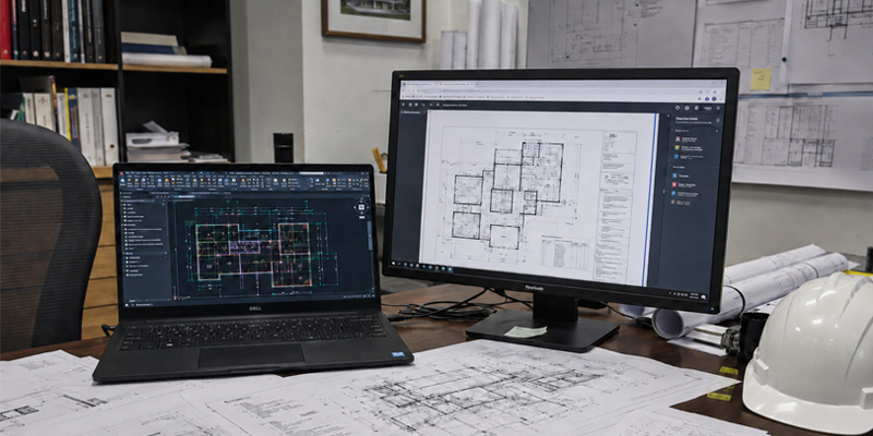
When it comes to updating drawings to as builts, block plans and evac plans, one of the most common questions we get is: “Do we need to send CAD files or can you work with the PDF’s?”

For Commercial Builders, fire safety is more than a regulatory requirement—it is a critical part of delivering a safe, compliant and fully operational facility to your client.
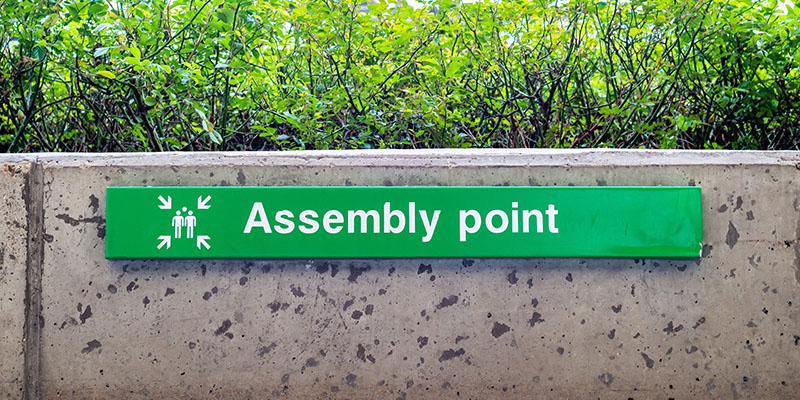
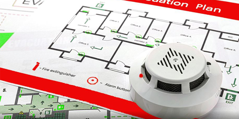
When it comes to safety in the workplace or any type of facility, few documents are as essential as the Evacuation Plan. These plans are not just good practice for health and safety — they’re a legal requirement.
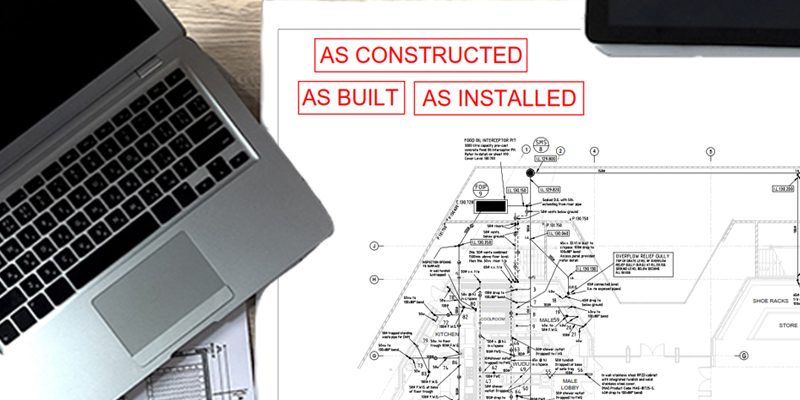
When working on construction projects, clear and accurate documentation is essential for ensuring regulatory compliance, effective asset management, and seamless future maintenance.

Fire safety is a critical aspect of building design and management. One key element in ensuring buildings and their occupants are protected is the development and maintenance of zone diagrams.

CAUTION: Need As Builts for the WA Department of Finance? Be prepared for cost increases. When it comes to submitting As Built Drawings to the Department of Finance (DOF) - Government of Western Australia, ensuring the files meet their required CADD protocol is not just a recommendation —it’s the requirement
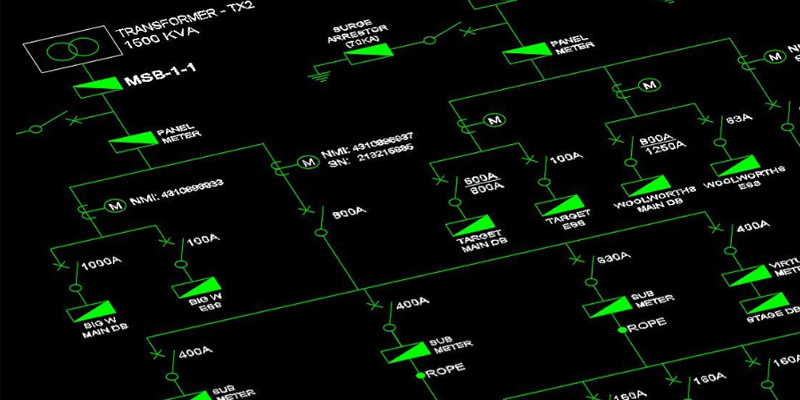
A Single Line Diagram (SLD) is a simplified representation of an electrical system, using standard symbols to represent components such as circuit breakers, transformers, busbars and cables.
Fire safety is a critical aspect of any building’s operational strategy. Whether you are responsible for a commercial building, educational facility, or residential complex, having a well-prepared and clearly communicated fire evacuation plan is essential.
Fire safety is a critical aspect of any building’s operational strategy. Whether you are responsible for a commercial building, educational facility, or residential complex, having a well-prepared and clearly communicated fire evacuation plan is essential.
Contact
 qr-code")
Follow Us
Address
Follow Us


© Design Assist Partners P/L 2024
© Design Assist Partners 2023


Welcome to Design Assist Partners, we deliver top-tier solutions for As-Builts, Fire Block Plans, Evacuation Plans and O&M Manuals. We’re committed to delivering an excellent client experience.
Quick Links
Follow Us
Contact Us
© Design Assist Partners Pty Ltd 2026
Privacy & Policy